
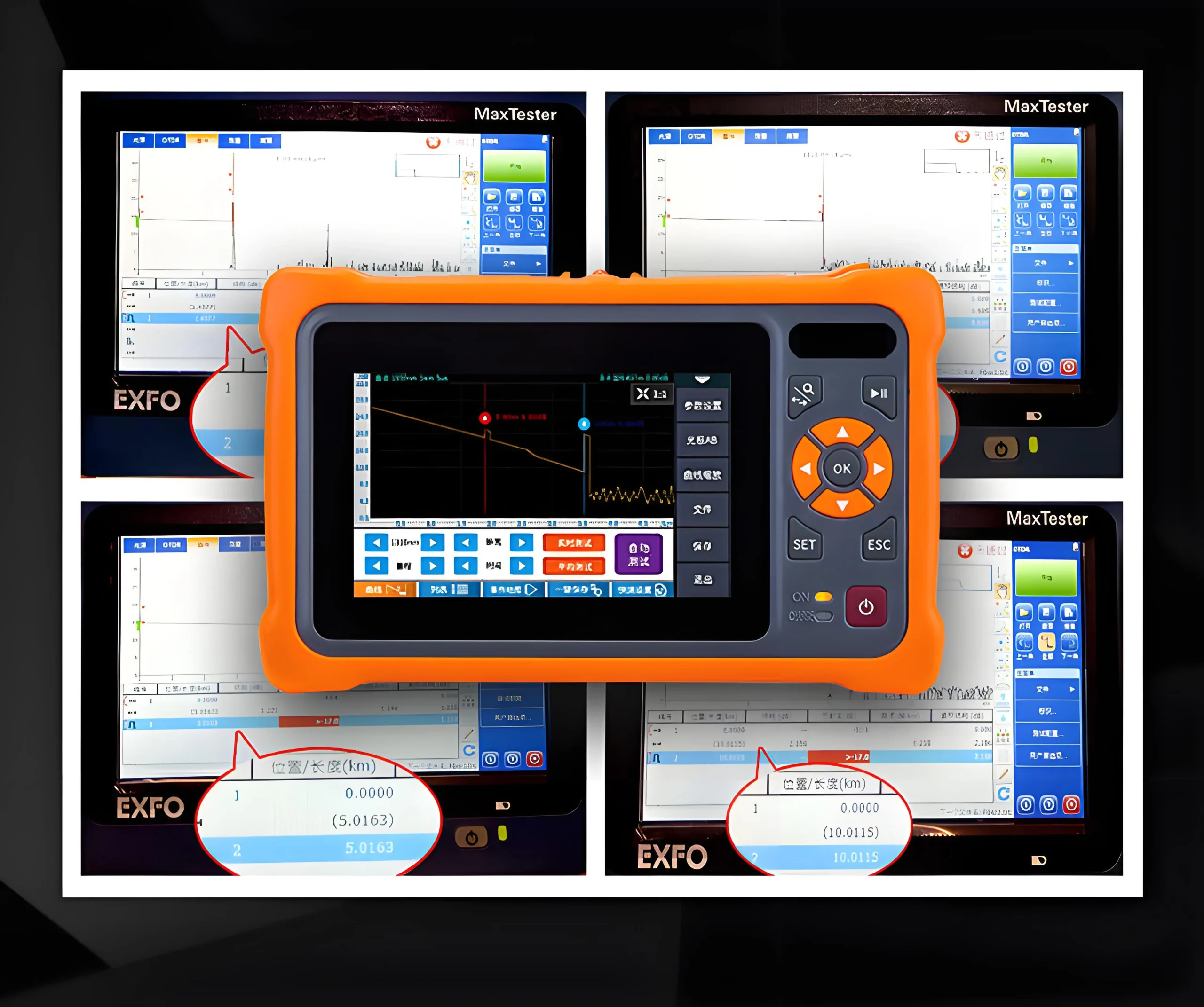
optical time-domain reflectometer,OTDR
Optical time-domain reflectometer (OTDR) is an instrument that analyzes the measurement curve to understand the uniformity, defects, breaks, joint coupling and other properties of optical fibers. It is made based on the backscattering and Fresnel reverse principle of light, and uses the backscattered light generated when light propagates in the optical fiber to obtain attenuation information. It can be used to measure optical fiber attenuation, joint loss, optical fiber fault point location, and understand the loss distribution along the length of the optical fiber. It is an indispensable tool in optical cable construction, maintenance and monitoring.
OTDR Principle Introduction
The distance can be calculated by determining the time it takes from the transmission of the signal to the return signal and then determining the speed of light in glass. The following formula explains how OTDR measures distance.
d=(c×t)/2(IOR)
In this formula, c is the speed of light in a vacuum, and t is the total time from the transmission of the signal to the reception of the signal (two-way) (multiplying the two values and dividing by 2 is the one-way distance). Because light is slower in glass than in a vacuum, in order to accurately measure the distance, the refractive index (IOR) of the optical fiber being measured must be specified. The IOR is indicated by the optical fiber manufacturer.
OTDR Detailed Introduction
The optical time domain reflectometer injects a series of light bursts into the optical fiber for inspection. The inspection method is to receive the optical signal on the same side as the injected burst, because the injected signal will be scattered and reflected back when encountering a medium with a different refractive index. The intensity of the reflected optical signal will be measured and is a function of time, so it can be converted into the length of the optical fiber.
The optical time domain reflectometer can be used to measure the length and attenuation of the optical fiber, including the fusion and transition points of the optical fiber. It can also be used to measure the break point when the optical fiber is broken.
The impact of the size of the OTDR dynamic range on the measurement accuracy
The DB difference between the initial backscattering level and the low noise level is defined as the dynamic range of the OTDR. Among them, the initial point of the backscattering level is the level value of the incident light signal, and the low noise level is the backscattering signal as an invisible signal. The size of the dynamic range determines the distance of the optical fiber that the OTDR can measure. When the level of the backscattering signal is lower than the OTDR noise, it becomes an invisible signal.
With the development of fiber fusion technology, people can control the loss of fiber joints below 0.1DB. In order to effectively observe all the fiber joints with small losses on the entire fiber, people need an OTDR with a large dynamic range. There are two main ways to increase the dynamic range of OTDR: increasing the initial backscattering level and reducing the low noise level. The factor that affects the initial backscattering level is the pulse width of the light. The factor that affects the low noise level is the scanning average time. Most models of OTDR allow users to select the optical pulse width parameter injected into the measured fiber. Under the same amplitude, a wider pulse will produce a larger reflection signal, that is, a higher backscattering level. In other words, the larger the optical pulse width, the larger the dynamic range of the OTDR.
The OTDR repeatedly sends pulses to the measured fiber and averages the curves of each scan to obtain the result curve. In this way, the random noise of the receiver will be suppressed as the averaging time increases. In the display curve of the OTDR, it is reflected that the noise level decreases with the increase of the averaging time, so the dynamic range will increase with the increase of the averaging time. In the initial averaging time, the dynamic range performance improves significantly, and in the following averaging time, the dynamic range performance improves significantly, and in the following averaging time, the dynamic range performance improves gradually. That is to say, the longer the averaging time, the larger the dynamic range of the OTDR.
The impact of blind zone on OTDR measurement accuracy
We call a series of “blind spots” caused by the saturation of the OTDR receiving end due to reflections generated by feature points such as active connectors and mechanical joints blind zones. The blind zones in optical fibers are divided into event blind zones and attenuation blind zones: the length distance from the starting point of the reflection peak to the receiver saturation peak caused by the intervention of active connectors is called the event blind zone; the distance from the starting point of the reflection peak to other identifiable event points caused by the intervention of active connectors in the optical fiber is called the attenuation blind zone. For OTDR, the smaller the blind zone, the better. The blind zone will increase with the increase of the pulse width. Although increasing the pulse width increases the measurement length, it also increases the measurement blind zone. Therefore, when testing optical fibers, we should use narrow pulses to measure the optical fiber and adjacent event points of the OTDR accessories, and use wide pulses to measure the far end of the optical fiber.
OTDR’s “gain” phenomenon
Since the fiber connector is a passive device, it can only cause loss but not “gain”. OTDR measures the loss of the connector by comparing the measured values of the backscattering level before and after the connector. If the scattering coefficient of the fiber after the connector is high, the backscattering level behind the connector may be greater than the scattering level before the connector, offsetting the loss of the connector, thus causing the so-called “gain”. In this case, the only way to obtain accurate connector loss is to use OTDR to test the connector from both ends of the fiber under test and average the two measurement results. This is to test the connector separately and average the two measurement results. This is the two-way average test method, which is currently a must-use method for fiber characteristic testing.
Can OTDR measure different types of optical fibers?
If a single-mode OTDR module is used to measure a multimode fiber, or a multimode OTDR module is used to measure a single-mode fiber, the measurement result of the fiber length will not be affected, but the results of fiber loss, optical connector loss, and return loss are incorrect. This is because when light is incident from a small-core fiber to a large-core fiber, the large core cannot be completely filled with the incident light, thus causing errors in loss measurement. Therefore, when measuring optical fiber, you must select an OTDR that matches the fiber being measured to perform the measurement, so that you can get the correct results for all performance indicators.
OTDR Main Features
1. ≤1m ultra-short event blind zone, easy to test fiber jumpers;
2. 45dB large dynamic range, 128k data sampling points;
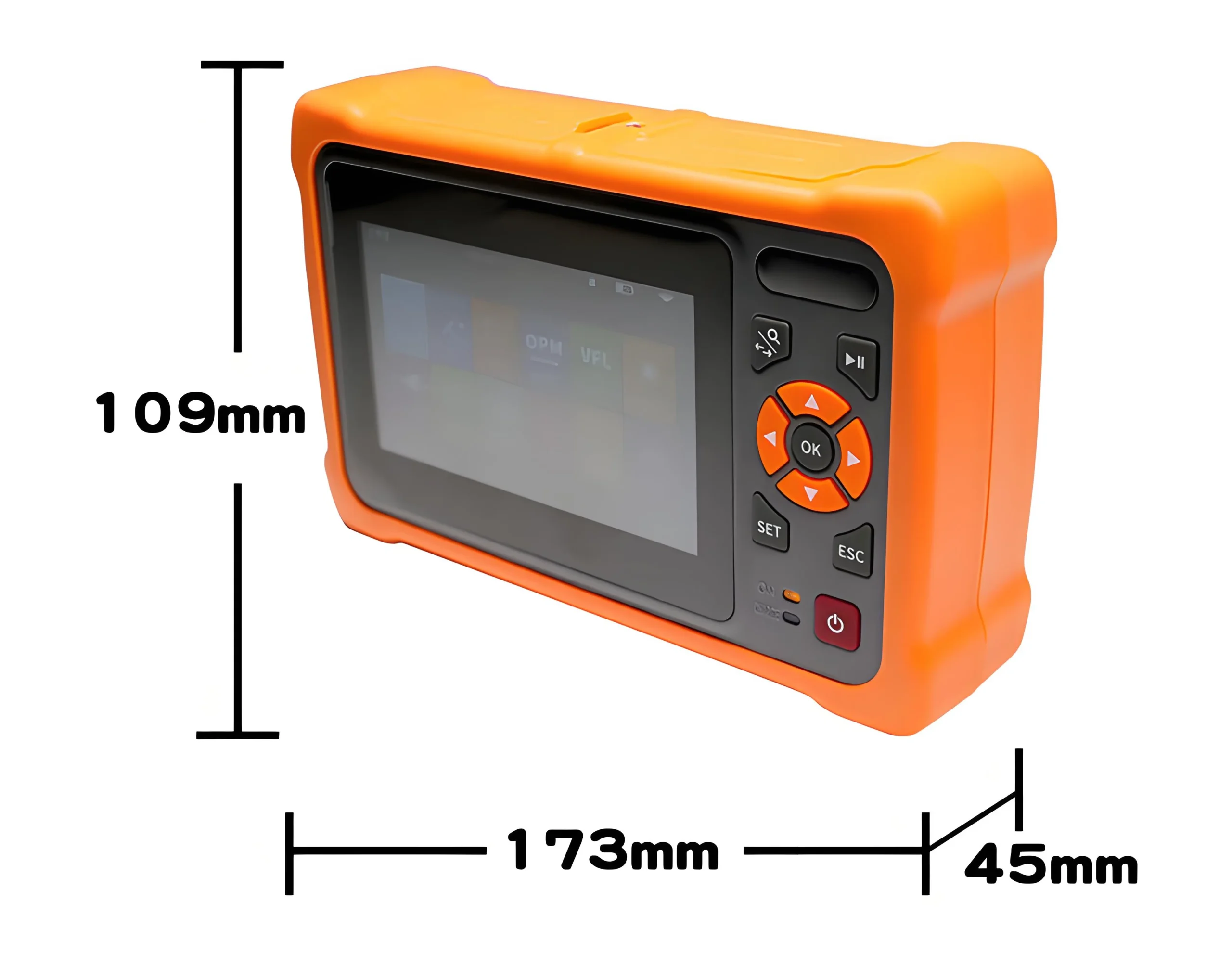
3. The industry’s most advanced dual-color dual-material integrated mold process, sturdy and durable;
4. Advanced anti-reflection LCD, the display interface is clearly visible in the field environment;
5. With multiple test modes, touch screen and quick key operation;
6. Communication light automatic monitoring function;
7. With Ethernet remote control function;
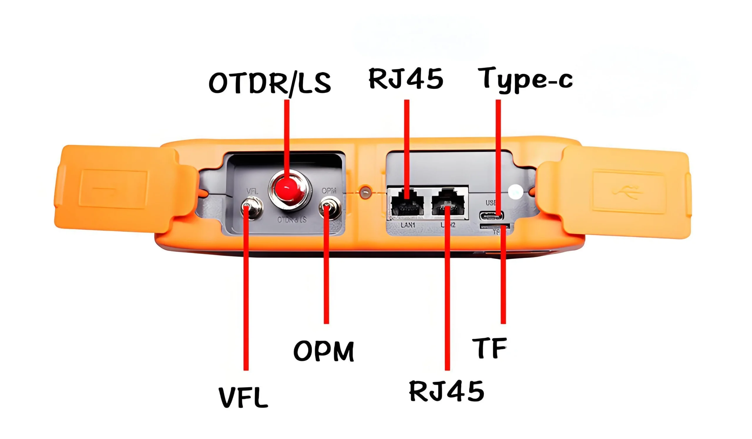
8. Dual USB interface function, can be connected to an external USB flash drive, printer and communicate with the PC through SyncActive software;
9. Support Bellcore GR196 and SR-4731 file formats;
10. Battery low voltage alarm function;
11. WinCE window operating system, Chinese and English operation interface;
12. Built-in visual red light fault location (VFL) and optical power meter function;
13. The type of OTDR optical output head can be replaced at will, and the end face cleaning is more convenient;
14. Built-in highly user-friendly multimedia teaching software, quickly become a testing expert;
15. Application software online upgrade, no need to return to the original factory
Dynamic Range
Dynamic range is an important OTDR parameter. This parameter reveals the maximum optical loss that the OTDR can analyze when the backscatter level at the OTDR port drops to a certain noise level. In other words, this is the maximum fiber length that can be reached with the longest pulse.
Therefore, the greater the dynamic range (in dB), the greater the reach. Obviously, the maximum distance will be different in different applications because the loss of the link under test is different. Connectors, splices, and splitters also contribute to the reduction of the maximum length of the OTDR. Therefore, averaging over a longer period of time and using the appropriate distance range is the key to increasing the maximum measurable distance. Most dynamic range specifications are given using a three-minute average of the longest pulse width, with a signal-to-noise ratio (SNR) = 1 (average level of the root mean square (RMS) noise value). Therefore, it is important to read the detailed test conditions noted in the specification footnotes.
Precautions for use
1. The optical output port must be kept clean. The optical output port needs to be cleaned regularly with anhydrous ethanol. The role of cleaning the optical fiber connector and optical output port 1. Since the optical fiber core is very small, dust and particles attached to the optical fiber connector and optical output port may cover part of the output optical fiber core, resulting in a decrease in instrument performance. 2. Dust and particles may cause wear on the end face of the output optical fiber connector, which will reduce the accuracy and repeatability of the instrument test
2. After using the instrument, cover the dust cap and keep the dust cap clean.
3. Clean the flange connector of the optical output port regularly. If cracks and fragments are found in the ceramic core in the flange, it must be replaced in time.
4. Properly set the light-emitting time to extend the service life of the laser source

 No products in the cart.