

MPO Cable Meaning
The MPO jumper cable is an economical alternative to complex and time-consuming on-site termination. It is purpose-built for high-density fiber patching in data center environments, where space optimization and easier cable organization are critical. Furthermore, its bend-insensitive fiber ensures consistent and reliable connection performance, even when installed in confined or sharply curved pathways.
MPO Patch Cable Advantage Specifications
Connector A:MPO (Pinless)
Connector B:MPO (Pinless)
Polish Type:PC to PC
Fiber Mode:OM3 50/125μm
Wavelength:850/1300nm
Fiber Count:8 Fibers
Polarity:Type C
Cable Outside Diameter (OD):3.0mm
Cable Jacket:Flame Retardant LSZH
Min. Bend Radius (Optical Fiber):7.5mm
Min. Bend Radius (Fiber Cable):20/10D (Dynamic/Static)
Connector Durability:500 times
Tensile Strength:90/180N (Long/Short Term)
Insertion Loss:0.35dB Max
Return Loss:≥25dB
Operating Temperature:-10 to 60°C (14 to 140℉)
Storage Temperature:-10 to 70°C (14 to 158℉)
MPO Cable Polarity
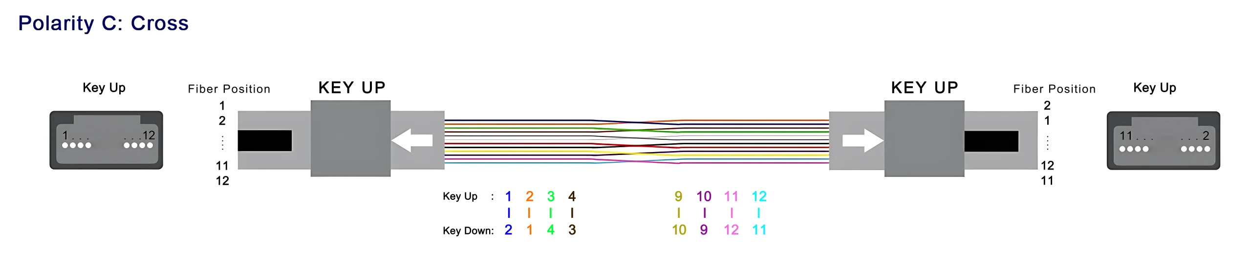
The MPO 8-fiber Type C female connector is a high-density fiber optic interface used in structured cabling systems, especially for duplex and parallel optical applications. It follows the Type C polarity (pairwise crossover), where adjacent fibers are swapped in pairs to ensure correct alignment of transmit (Tx) and receive (Rx) signals.
For example:
- Fiber 1 ↔ Fiber 2
- Fiber 2 ↔ Fiber 1
- Fiber 3 ↔ Fiber 4
- Fiber 4 ↔ Fiber 3
- ……..
- Fiber 9 ↔ Fiber 10
- Fiber 10 ↔ Fiber 9
- Fiber 11 ↔ Fiber 12
- Fiber 12 ↔ Fiber 11
This pairwise flipping ensures that each Tx fiber is properly connected to the corresponding Rx fiber without requiring additional polarity conversion.
As a female connector, it does not include guide pins and is designed to mate with a male MPO connector (with pins), ensuring accurate fiber alignment and stable optical performance.
MPO Cable Polarity Key Features:
Connector type: MPO 8-fiber female (without pins)
Fiber count: 8 fibers in a single-row MT ferrule
Polarity standard: Type C (pairwise crossover mapping)
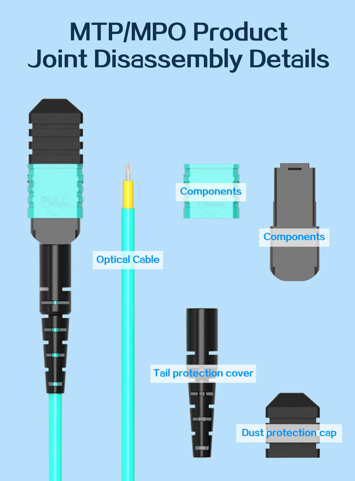
Ferrule design: Precision MT ferrule for low insertion loss and high repeatability
Cable jacket options: OFNR, OFNP, or LSZH, with standard fiber color coding (yellow for OS2, aqua/violet for OM3/OM4, lime green for OM5)
MPO Cable Connector Advantage
- Correct Tx/Rx mapping: Pairwise crossover ensures proper signal alignment
- High-density connectivity: 8 fibers in one compact interface reduce cable congestion
- Reliable mating: Female connector pairs with male (pinned) connector for precise alignment
- Flexible deployment: Suitable for duplex and parallel optics environments
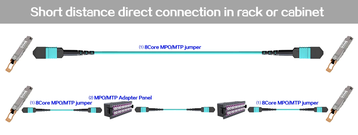
MPO Fiber Patch Cords Short distance direct connection in rack or cabinet
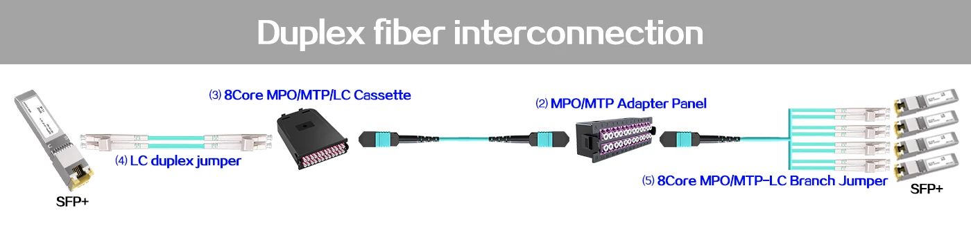
Fiber Optic MPO Patch Duplex fiber interconnection
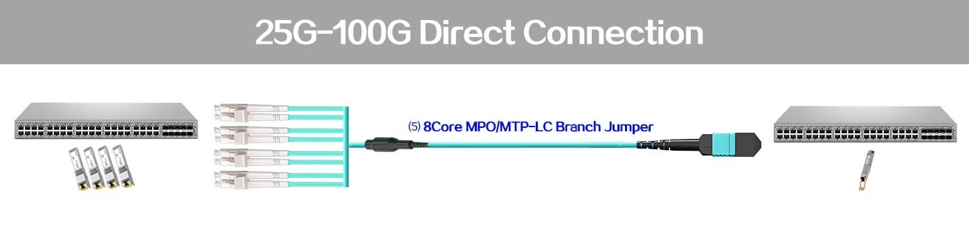
MPO Jumpers 25G-100G direct connection
You can connect one 100G QSFP28 SR4 optical module to four 25G SFP28 SR optical modules through an 8-core MPO/MTP to four duplex LC multimode breakout cable. Similarly, you can connect one 100G QSFP28 PSM4 optical module to four 25G SFP28 LR optical modules through an 8-core MPO/MTP to four duplex LC multimode breakout cable.
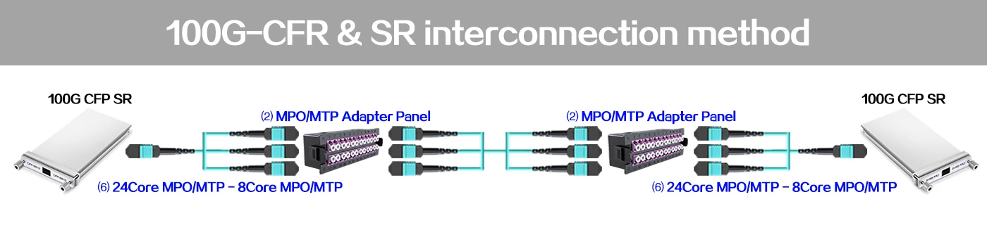
MPO Fiber Patch 100G-CFR&SR interconnection method
The solution is to connect from one 100G CFP optical module to another CFP using a 24-core MPO/MTP to 3×8-core MPO/MTP breakout cable.
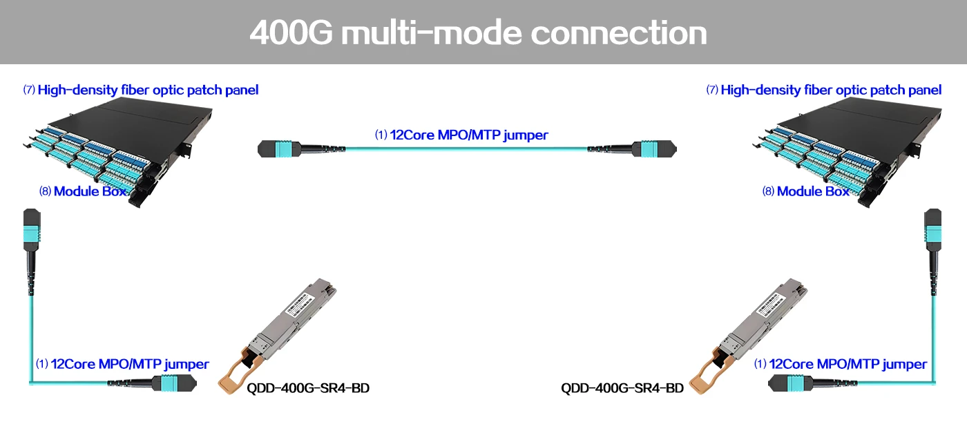
MPO Cable 400G multi-mode connection
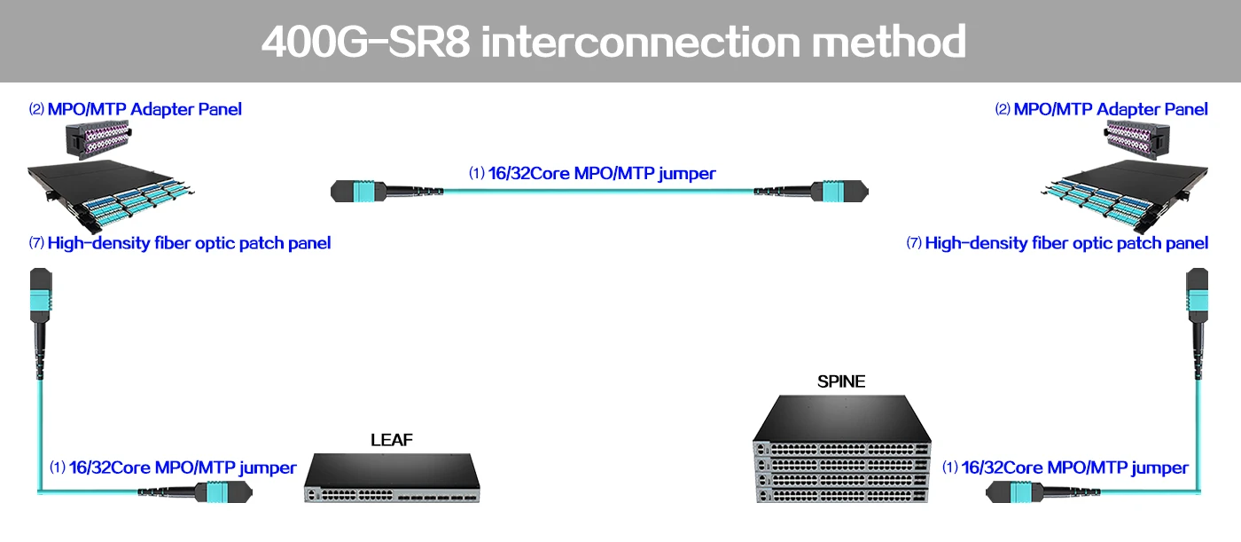
MPO Fiber Patch cord 400G-SR8 interconnection method
The 400G QSFP-DD SR8 optical module uses a standard MPO-16 connector to achieve 400G transmission. The transmission distance through multimode optical fiber can reach up to 70m (OM3) or 100m (OM4).
MPO Patch Cable Application
High-speed interconnection in data centers
It is used for direct connection of 40G/100G optical modules, supports 400G high-speed transmission, and can improve wiring density and transmission efficiency. For example, 400G QSFP-DD DR4 optical modules can be directly connected through MPO/MTP-8 multimode fiber jumpers.
High-density wiring scenarios
In the backbone wiring of data centers, MTP/MPO trunk fiber jumpers are used in conjunction with adapter modules to achieve interconnection and cross-connection between devices, saving 45% of wiring space. Branch jumpers are used to connect devices with different rates (such as 10G and 40/100G devices).
100G/400G transmission expansion
Supports branch connection of 100G QSFP28 optical modules to 4 25G SFP28 optical modules, or interconnection of 100G CFP optical modules to another CFP.
Fiber-to-Building Applications
It is used for fiber-to-the-building (FTTB) wiring to meet the needs of high-density fiber access.

MPO Cable Tester Series
MPO Patch Cable Polarity Test Process
End face cleaning: Use special equipment to remove end face contaminants to avoid affecting the test accuracy.
Morphology detection: Analyze the end face microstructure through 3D imaging technology to detect surface roughness, scratches and other defects.
Insertion loss test: Measure the contact loss between the fiber end face and the connector ferrule to evaluate the signal transmission quality.
Polarity verification: Confirm the correspondence between the number of fiber cores and the connector guide hole to prevent communication failure caused by wrong connection.
MPO Fiber Patch Cords Test Key Indicators
Cleaning efficiency: It must reach more than 98% to ensure that there are no residual stains on the end face.
Detection accuracy: The resolution of 3D morphology detection must be less than 1.5μ, and the insertion loss error must be controlled within 0.3dB.
Test time: It takes about 10 seconds to detect a single fiber core of a 12-core MPO jumper, and the overall test takes about 2 minutes.
MPO Fiber Jumper Test Common Problems
Pollution sensitivity: Tiny particles on the end face will cause increased loss, and non-contact cleaning methods are required to protect the end face.


 No products in the cart.
Reviews
There are no reviews yet.