
Fiber Patch Cables Type
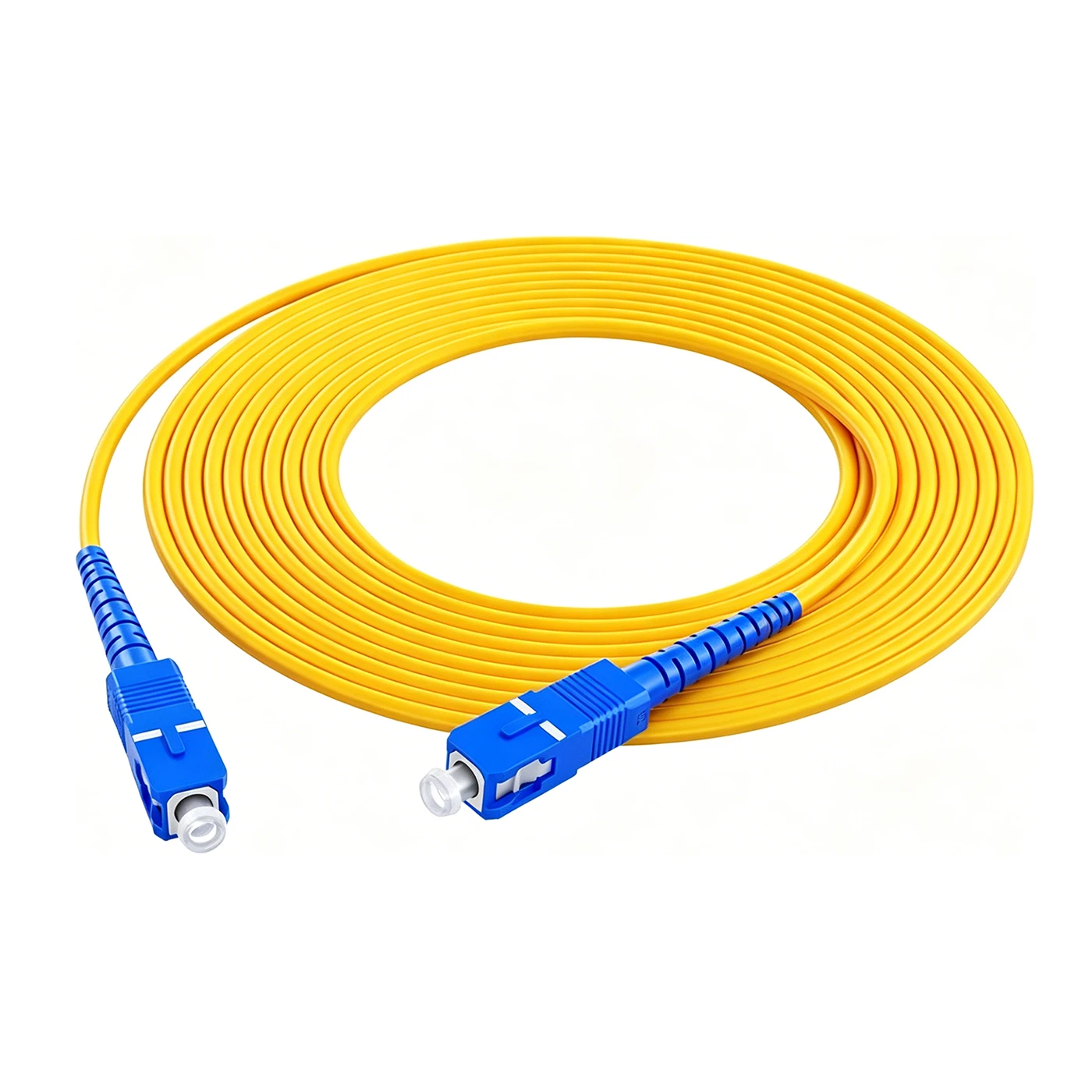
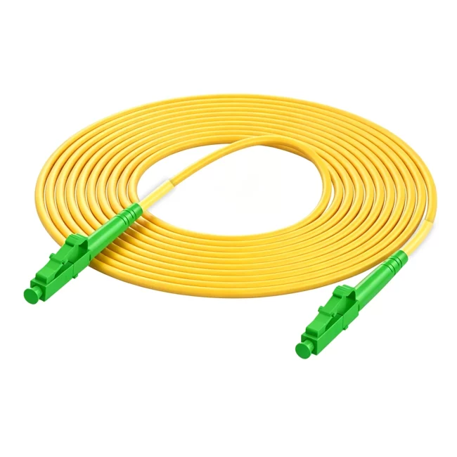
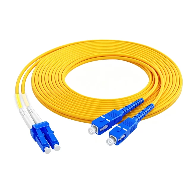
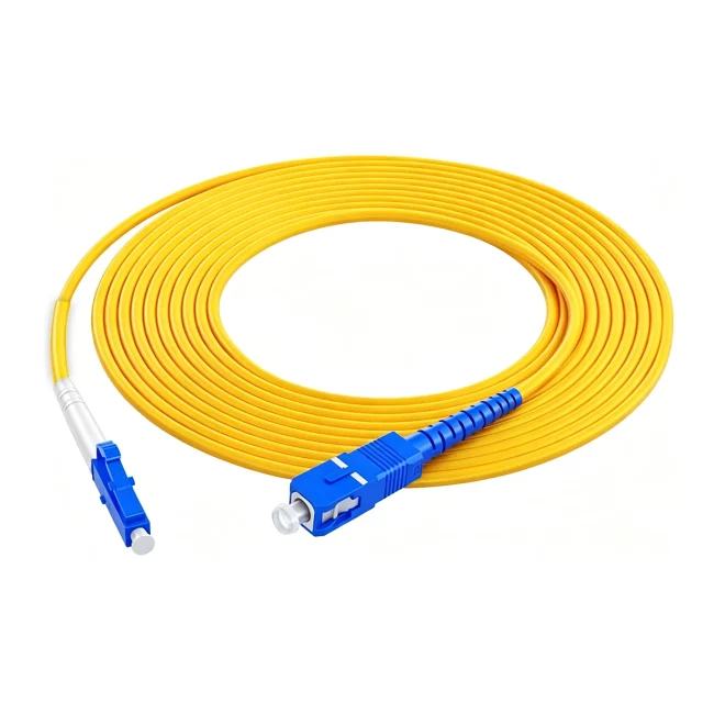
Designed for high-speed optical networking, the fiber optic patch cord provides secure and efficient connections between optical devices and structured cabling systems. Its robust jacket enhances durability, while factory-terminated connectors ensure consistent optical performance. Suitable for use in data centers, enterprise LANs, telecommunications networks, FTTx infrastructures, and other mission-critical fiber optic applications.
Fiber Jumper Cables Advantage Specifications
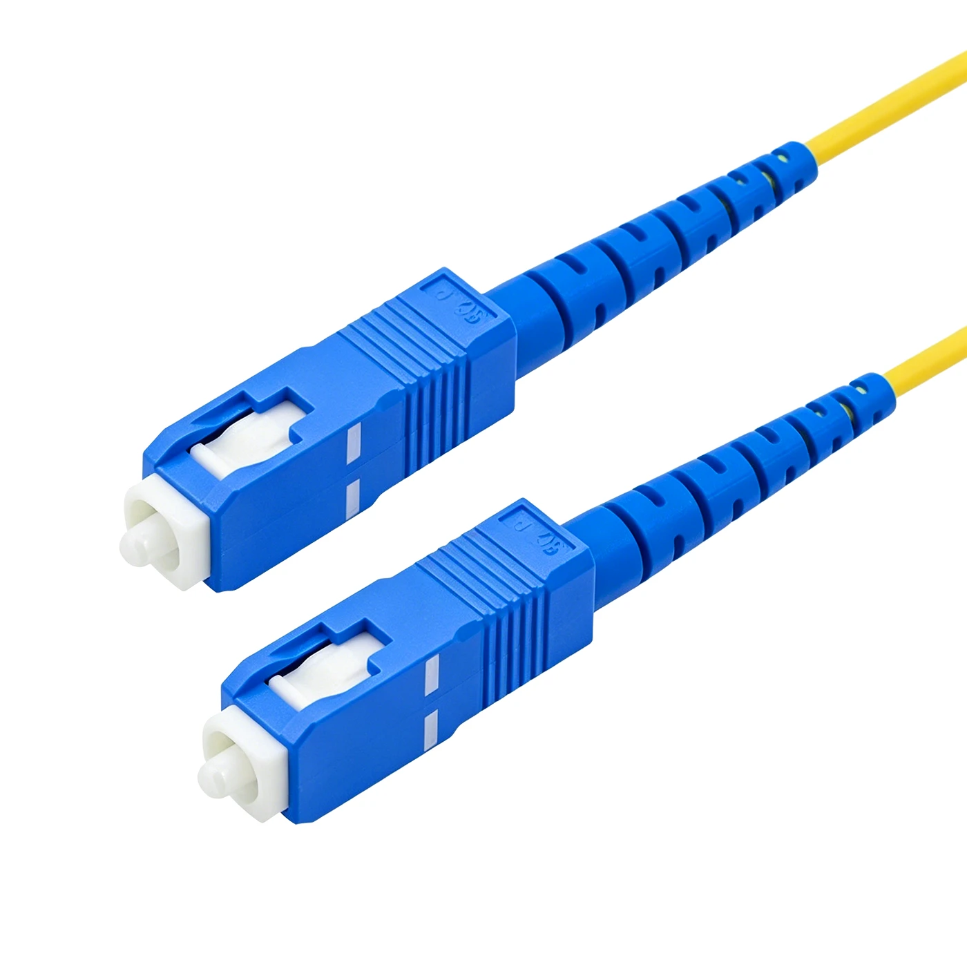
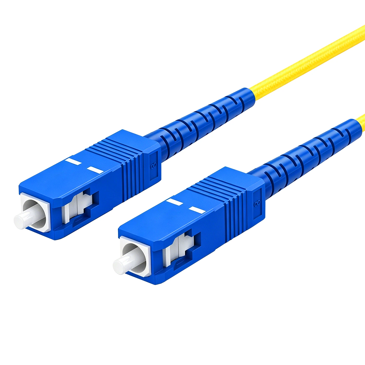
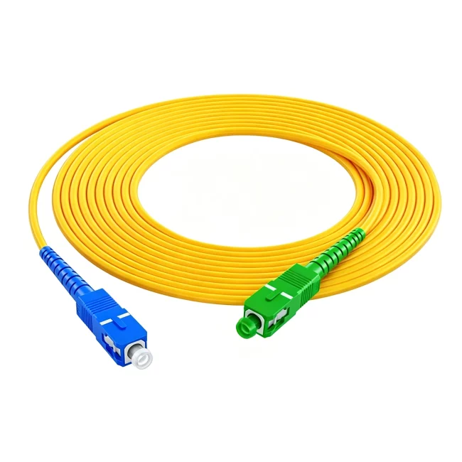
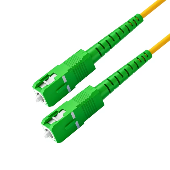
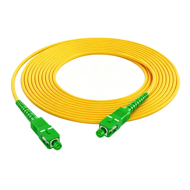
Connector A:SC UPC Simplex
Connector B:SC UPC Simplex
Fiber Mode:OS2 9/125μm(G657A1),(Compatible with G.652.D)
Wavelength:1310/1550nm
Fiber Count:1 Fibers
Cable Type:Tight-Buffered
Cable Outside Diameter (OD):2.0mm
Cable Jacket:Riser (OFNR)
Min. Bend Radius (Optical Fiber):10mm
Min. Bend Radius (Fiber Cable):10/5D (Dynamic/Static)
Connector Durability:1000 times
Tensile Strength:60/100N (Long/Short Term)
Insertion Loss:0.30dB Max
Return Loss:≥50dB
Attenuation at 1310nm:≤0.4dB/km
Attenuation at 1550nm:≤0.3dB/km
Operating Temperature:-10 to 70°C (14 to 158℉)
Storage Temperature:-20 to 70°C (-4 to 158℉)
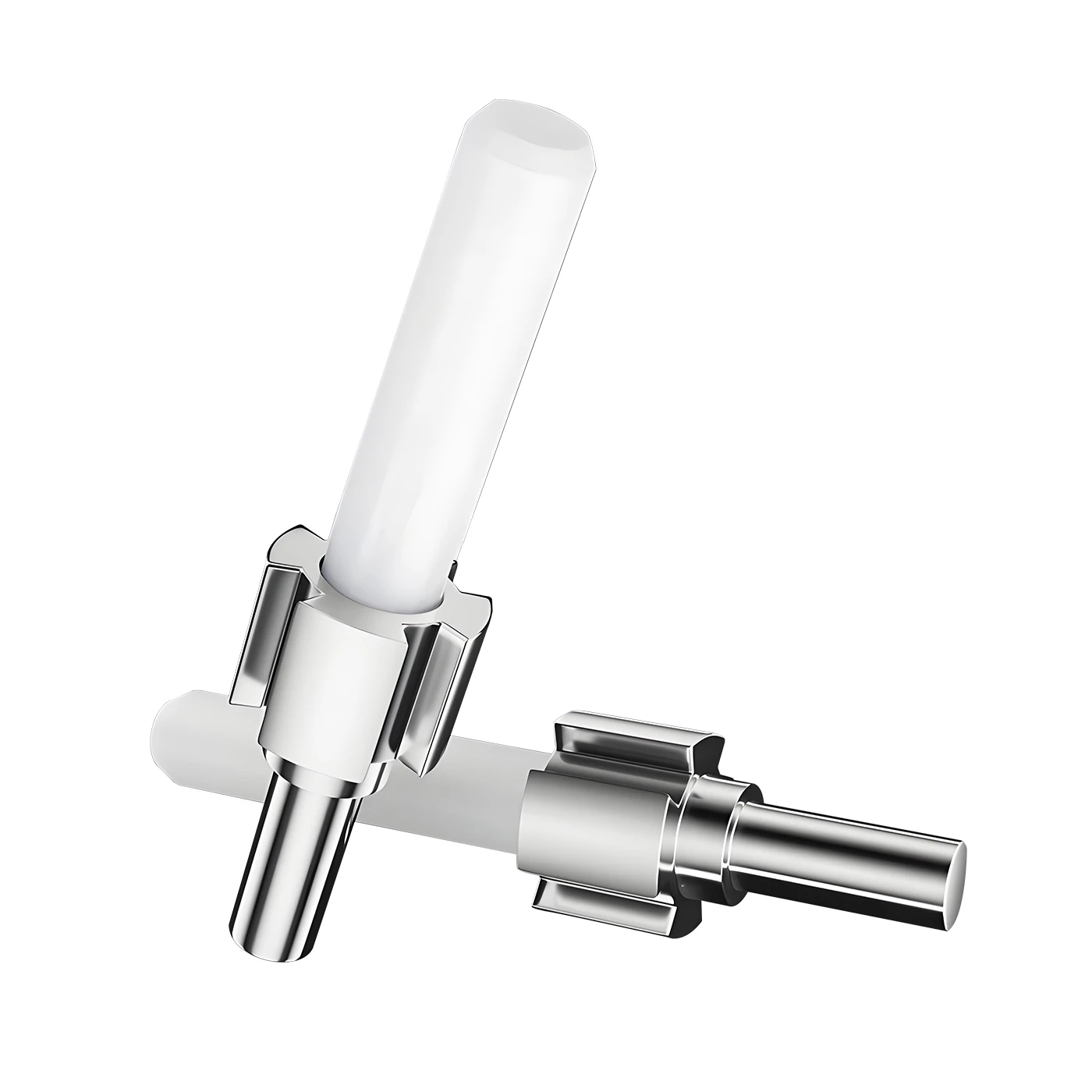
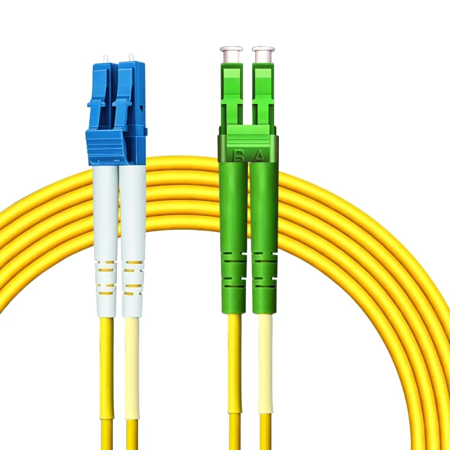
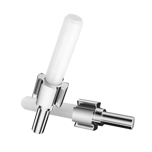
Fiber Jumper Cable Structure
Fiber Optic Patch Cord (also known as a Fiber Optic Jumper) is a length of fiber optic cable with connectors attached to both ends, enabling detachable optical connections; a cable with a connector on only one end is called a pigtail. Fiber optic patch cords are similar to coaxial cables but lack the braided shielding layer. At the center lies a glass core that transmits light. In multimode fiber, the core diameter is 50–65 μm—roughly the thickness of a human hair—whereas single-mode fiber has a core diameter of 8–10 μm. Surrounding the core is a glass cladding layer with a lower refractive index, which keeps the light confined within the core. An outer thin plastic jacket protects the cladding.

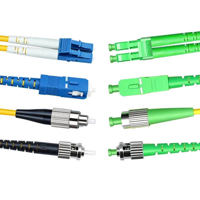
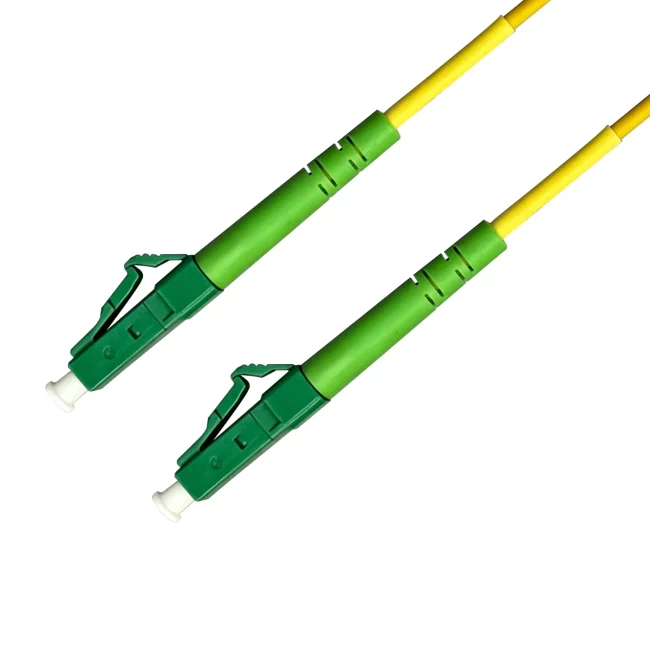
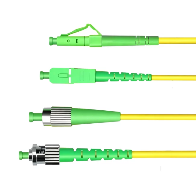
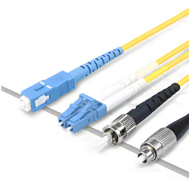
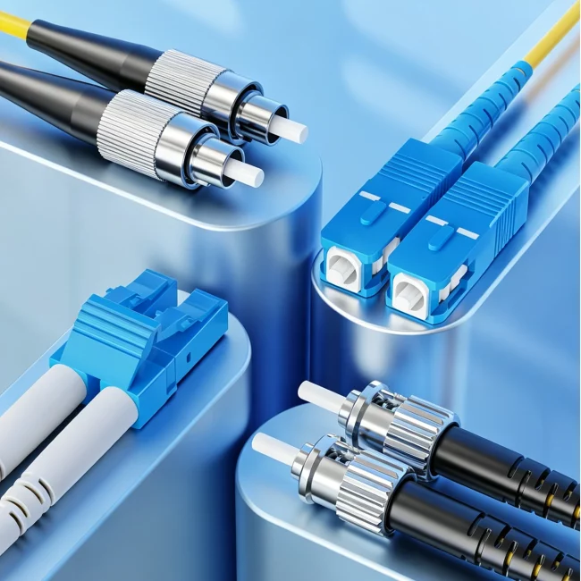
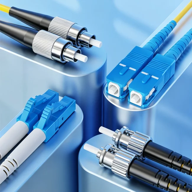
Fiber Jumper Connector Types
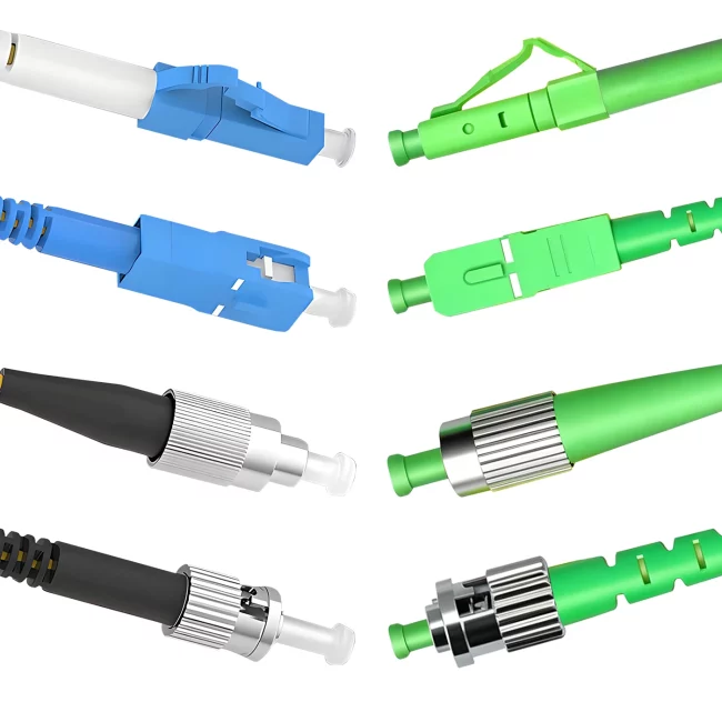
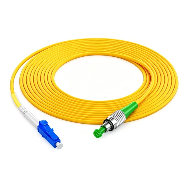
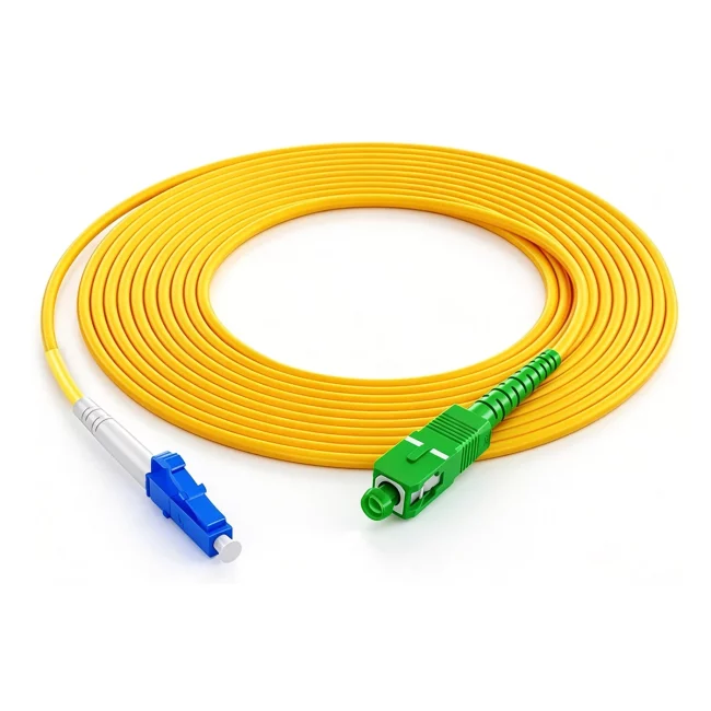
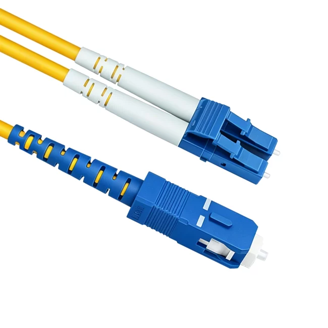
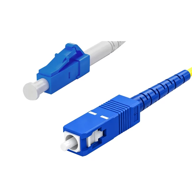
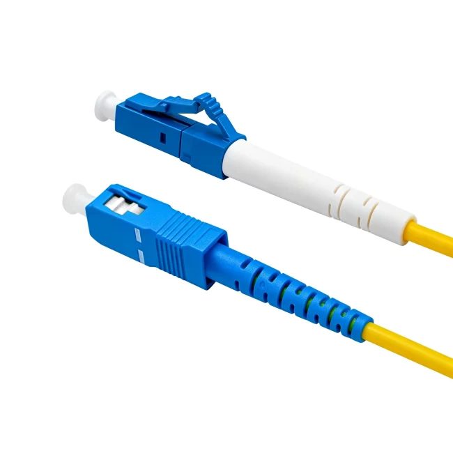
Fiber optic patch cords (also known as fiber optic jumpers)—the connectors that plug into optical modules—come in various types that are not interchangeable. For instance, SFP modules connect to LC connectors, while GBIC modules connect to SC connectors. Below are detailed descriptions of several common fiber optic connectors used in network engineering:
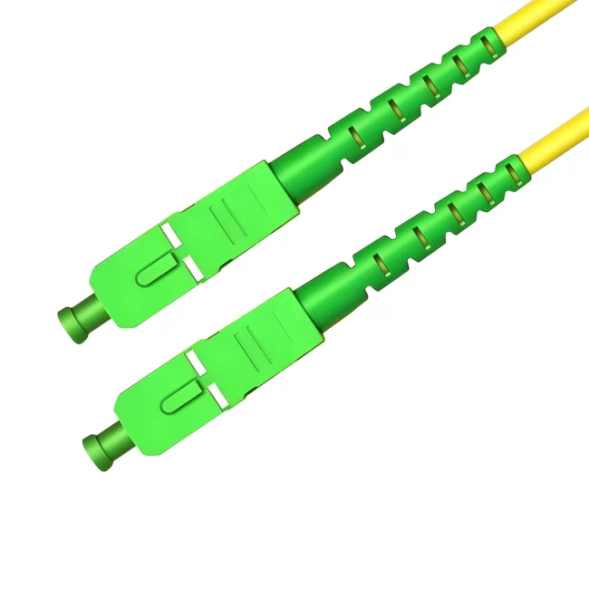
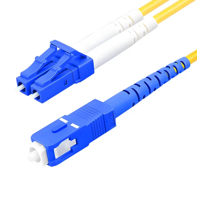
① SC-type fiber optic patch cord: Connects to GBIC optical modules; it has a rectangular housing and uses a push-pull latching mechanism that requires no rotation. Commonly used on routers and switches.
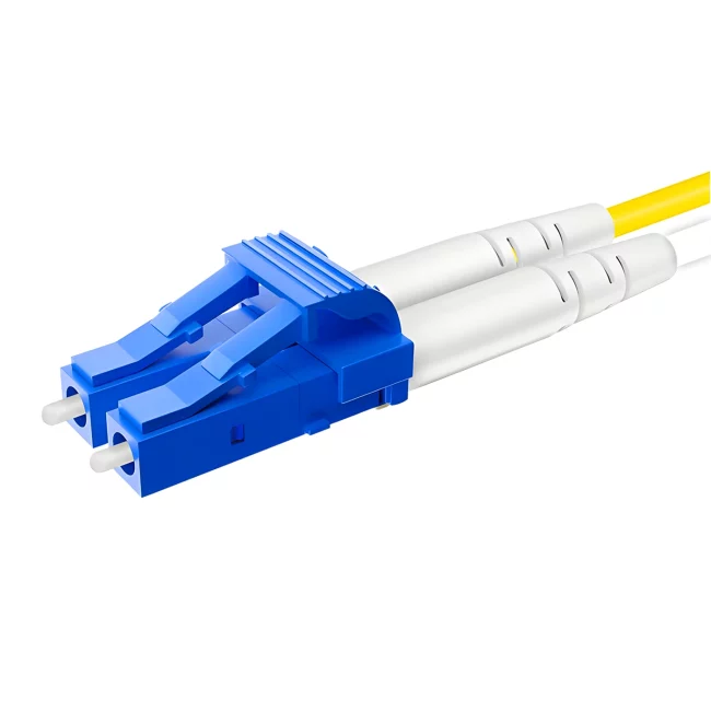
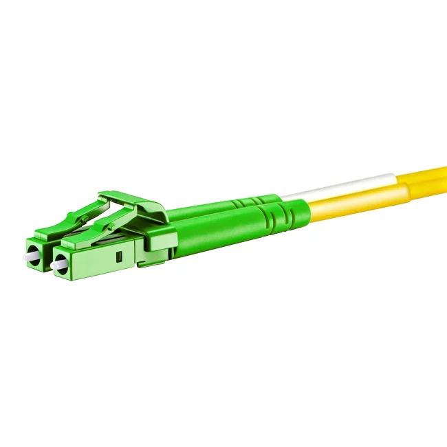
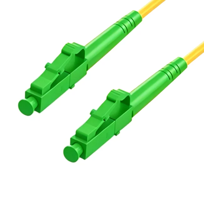
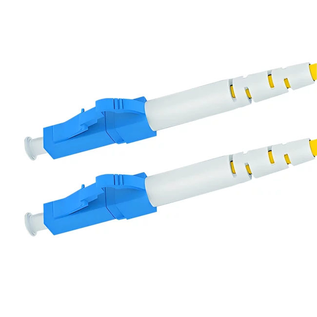
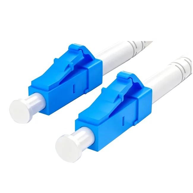
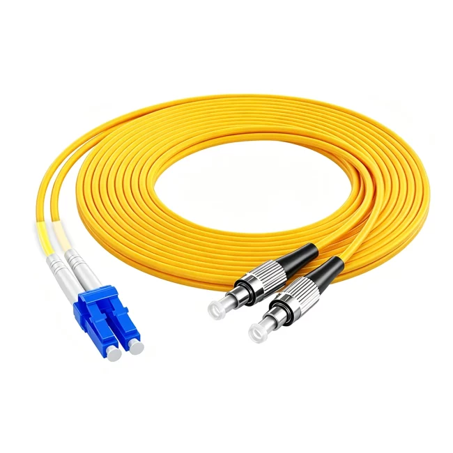
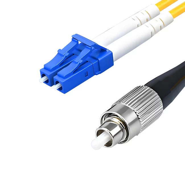
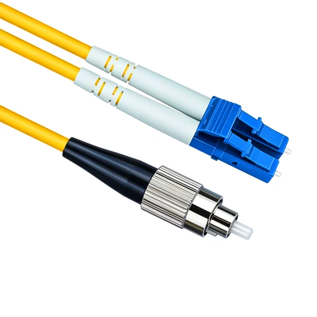
② LC-type fiber optic patch cord: Connects to SFP modules; it utilizes a user-friendly modular jack (RJ-style) latching mechanism. Commonly used on routers.
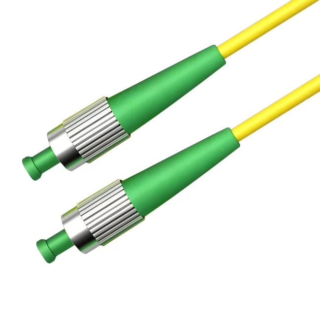
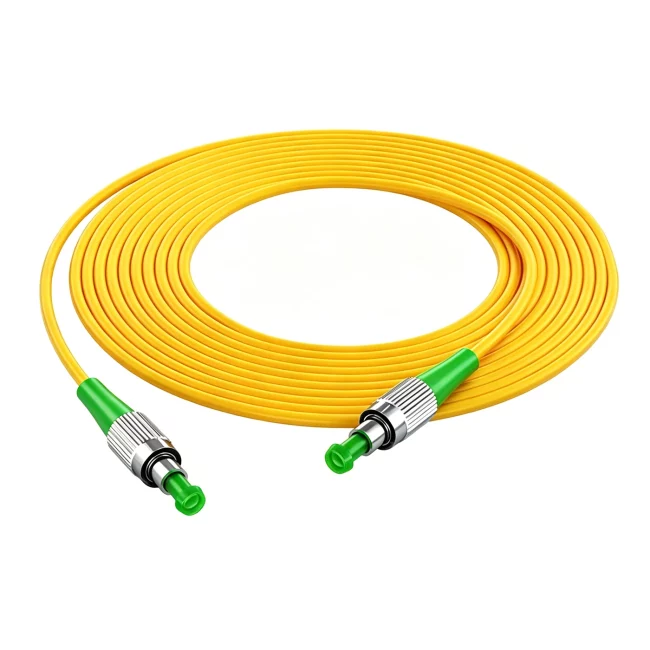
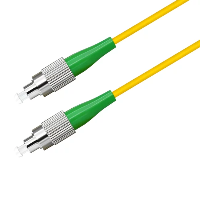
③ FC-type fiber optic patch cord: Features a metal sleeve for external reinforcement and a screw-thread fastening mechanism. Typically used on the ODF (Optical Distribution Frame) side.
④ ST-type fiber optic patch cord: Often used with fiber optic distribution frames; it features a round housing and a screw-thread fastening mechanism. (Commonly used for 10Base-F connections and fiber optic distribution frames.)

Fiber Jumper Cable Features:
1. Low insertion loss;
2. Good repeatability;
3. High return loss;
4. Good inter-mateability;
5. Good temperature stability;
6. High tensile strength.

Fiber Jumpers Applications
Fiber optic patch cords are widely used in applications such as telecommunications equipment rooms, Fiber-to-the-Home (FTTH), local area networks (LANs), fiber optic sensors, fiber optic communication systems, fiber optic transmission equipment, and national defense systems. They are suitable for use in cable TV networks, telecommunications networks, fiber optic computer networks, and optical testing equipment. Specific applications include:
1. Fiber optic communication systems
2. Fiber optic access networks
3. Fiber optic data transmission
4. Fiber optic CATV
5. Local Area Networks (LANs)
6. Testing equipment
7. Fiber optic sensors

Fiber Jumper Cables Detection
Performance testing for fiber optic patch cords falls into the following categories:
1. Optical performance testing: Includes return loss and insertion loss measurements. The FibKey 7602 integrated return loss/insertion loss tester is commonly used for this purpose.
2. End-face geometry testing: Parameters measured include radius of curvature, apex offset, and fiber height. Interferometers are used for this testing; the Norland AC/NC3000 or CC6000 models are widely adopted. The CC6000, in particular, is increasingly used in factories due to its excellent cost-performance ratio.
3. Fiber end-face scratch inspection: Video fiber microscopes are used for observation; for example, many factories use the FibView FV-400PA. This instrument provides exceptionally clear images and is extremely easy to operate. Some customers also use the FibKey-5600 variable-magnification microscope, which integrates 400x, 200x, and 80x magnification capabilities, allowing for clear and convenient inspection of both the fiber end-face and the ferrule end-face. Automated inspection using specialized software is also an option.
4. Fiber tensile testing: Measures the tensile force that the fiber optic connector can withstand.
5. Environmental temperature testing: Evaluates the performance metrics of the fiber optic connector under varying ambient temperatures.


 No products in the cart.
Reviews
There are no reviews yet.